Road Intersections | What is a road intersection?
On-road, intersection conflicting vehicle movements at junctions are a major cause of accidents in many developing countries. A small number of well-designed junctions along a route is preferable to a large number of low-quality junctions. Simple crosswords have a very bad accident record.
Crossroads with two consecutive T-junctions on opposite sides of the road reduce the accident rate. It may be appropriate to use roundabouts, traffic lights, and channelization to improve vehicle flow and safety.
Collisions can often be eliminated by the expensive solution of grade separation, but it is usually not necessary to design for free-flow conditions due to traffic capacity requirements. For
Relatively high traffic rates, especially in urban areas, are more suited to improving vehicle flow with traffic light control.
The intersection spacing should be as regular as possible to allow an efficient traffic light phase on the main road if traffic lights are needed or installed in the future. The distance guide is given by:
D=0.139·€.V
where:
D=spacing of intersections (metres);
C=cycle time (sec);
V=vehicle speed (kmh−1).
Staggered intersections
Where information on the traffic volumes or relative importance of two crossing roads enables the designer to distinguish between the major road and the minor road a staggered intersection should be used wherever possible.
In the case of cross intersection angles outside the acceptable range, the minor road can be realigned using staggered intersections as shown in Figure 8.6.

The staggered intersections are referred to as ‘left-right or ‘right-left according to the vehicle’s turning movements on a small road crossing the main road. If the volume of small road traffic is negligible, the distraction should be designed to avoid crossing major road traffic at the turning point of the main road.
As a result, left-right distraction is not recommended for left-handed driving and right-left driving is undesirable for right-handed driving. The minimum distance between the legs of the transverse incision should be 100 m.
In the case of intersections with tapered deceleration/acceleration lanes, the minimum spacing should, however, be 200 m.
Maximum gradient
In order to permit heavy vehicles to operate at reasonable acceleration rates within the vicinity of the intersection, it is desirable that the maximum longitudinal gradient of any leg of an intersection is 3.0%. This is also the maximum gradient allowed on the intersecting road within 30m of the point of intersection of the center lines of the respective roads.
Intersection layout
Typical intersection designs for left-handed driving traffic are presented in Figures 8.7, 8.8 and 8.9. The intersections in Figure 8.7 are used for low-volume roads and property access. These intersections are not represented by any of the islands or
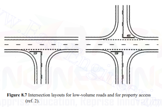


widening. The edge of the pavement is constructed as a single circular arc with a radius 8– 10m. For private property access, the radius is reduced to 6m.
The intersections in Figure 8.8 are used for low-volume small roads, with traffic lightly turning from major to minor. They are characterized by the introduction of the sectional island and the widening of the small road.
The edge of the pavement is constructed as a three-point curve consisting of three circular arcs.
The intersections in Figure 8.9 provided the sectional island and channelized main road widening, allowing traffic to pass right through traffic.
Islands
Generally, curbed islands that are potential hazards should only be introduced when the risk of removal is lower or greater than the risk they introduce. Channelisation with islands in the middle of the main road (cf. Figure 8.9) should be established by hatched islands (ghost islands) painted in rural areas and not by restricted islands.
Three-point curve When the edge of the carriageway is designed with a three-point curve (cf. Figures 8.8 and 8.9), the following ratios between the radii and the center angles should be used.
RI :R2:R3 = 2.S: I :S.S
A1:A2:A3 = 1:5.5:1
The tangent angle A is determined through the following equation (Figure 8.10).
A= Al + A2 +A3
The radius R2 of the middle circular arc is chosen according to Table 8.6 depending on the design vehicle.

Also, Read