Deep Foundations
Caissons A caisson, or drilled pier (Figure 2.37), is similar to a column footing in that it spreads the load from a column over a large enough area of soil that the allowable stress in the soil is not exceeded. It differs from a column footing in that it extends through strata of unsatisfactory soil beneath the substructure of a building until it reaches a more suitable stratum. A caisson is constructed by drilling or hand-digging a hole, belling (fl aring) the hole out at the bottom as necessary to achieve the required bearing area, and fi lling the hole with concrete. Large auger drills
(Figures 2.38 and 2.39) are used for drilling caissons; hand excavation is used only if the soil is too full of boulders for the drill. A temporary cylindrical steel casing is usually lowered around the drill as it progresses to support the soil around the hole. When a fi rm bearing stratum is reached, the bell, if required, is created at the bottom of the shaft either by hand excavation or by a special belling bucket on the drill
(Figure 2.40). The bearing surface of the soil at the bottom of the hole is then inspected to be sure it is of the anticipated quality, and the hole is fi lled with concrete, withdrawing the casing as the concrete rises. Reinforcing is seldom used in the concrete except near the top of the caisson, where it joins the columns of the superstructure. Caissons are large, heavy-duty foundation components. Their shaft
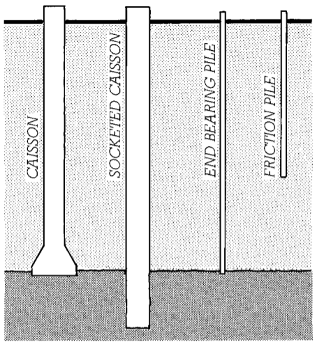
Figure 2.37 Deep foundations. Caissons are concrete cylinders poured into drilled holes. They reach through weaker soil (light shading) to bear on competent soil beneath. The end bearing caisson at the left is belled as shown when additional bearing capacity is required. The socketed caisson is drilled into a hard stratum and transfers its load primarily by friction between the soil or rock and the sides of the caisson. Piles are driven into the earth. End bearing piles act in the same way as caissons. The friction pile derives its load-carrying capacity from friction between the soil and the sides of the pile.
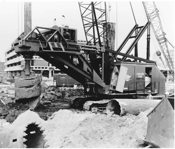
Figure 2.38 A 6-foot- (1828-mm)-diameter auger on a telescoping 70-foot (21-m) bar brings up a load of soil from a caisson hole. The auger will be rotated rapidly to spin off the soil before being reinserted in the hole. (Courtesy of Calweld Inc.)
Also Read: Shallow Foundation
diameters range from 18 inches (460 mm) up to 8 feet (2.4 m) or more. Belled caissons are practical only where the bell can be excavated in a cohesive soil (such as clay) that can retain its shape until concrete is poured. Where groundwater is present, the temporary steel casing can prevent fl ooding of the caisson hole during its construction. But where the bearing stratum is permeable, water may be able to fi ll the hole from below and caisson construction may not be practical.
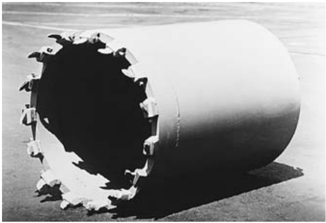
Figure 2.39 For cutting through hard material, the caisson drill is equipped with a carbide-toothed coring bucket. (Courtesy of Calweld Inc.)
A socketed caisson (Figure 2.37) is drilled into rock at the bottom rather than belled. Its bearing capacity comes not only from its end bearing, but from the frictional forces between the sides of the caisson and the rock as well. Figure 2.41 shows the installation of a rock caisson or drilled-in caisson, a special type of socketed caisson with a steel H-section core.
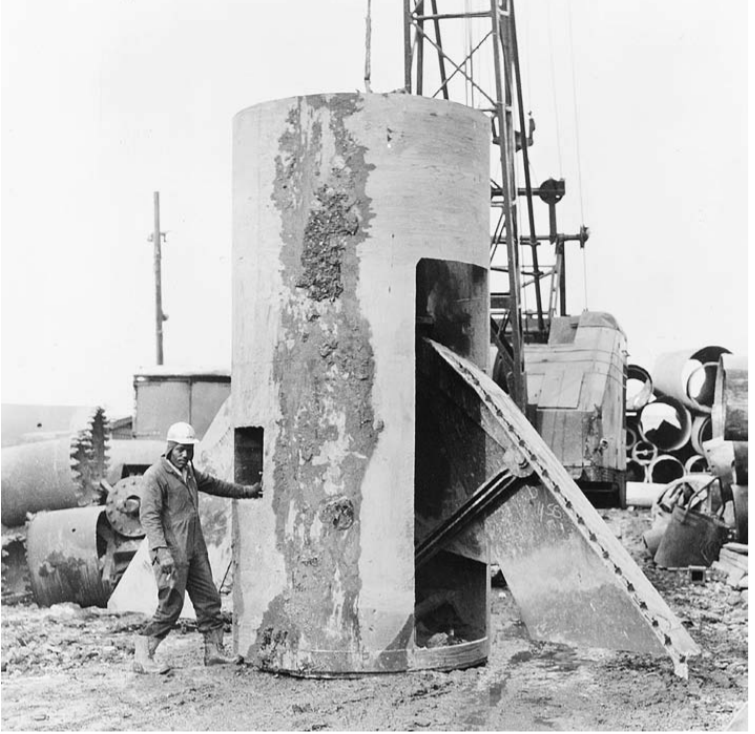
Figure 2.40 The bell is formed at the bottom of the caisson shaft by a belling bucket with retractable cutters. The example shown here is for an 8-foot- (2.44-m)-diameter shaft and makes a bell 21 feet (6.40 m) in diameter. (Courtesy of Calweld Inc.)
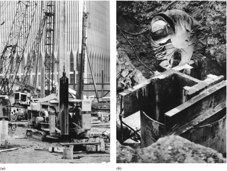
Figure 2.41
Installing a rock caisson. (a) The shaft of the caisson has been drilled through softer soil to the rock beneath and cased with a steel
pipe. A churn drill is being lowered into the casing to begin advancing the hole into the rock. (b) When the hole has penetrated the
required distance into the rock stratum, a heavy steel H-section is lowered into the hole and suspended on steel channels across the
mouth of the casing. The space between the casing and the H-section is then fi lled with concrete, producing a caisson with a very high
load-carrying capacity because of the composite structural action of the steel and the concrete. (Courtesy of Franki Foundation Company)